| 4 |
Electricity
and Magnetism
|
Where to go! |
| 4.6 |
Introductory
Electronics
|
|
C
|
Action and use of circuit
components
|
|
| Core-1 |
Describe the action
of a variable potential divider (potentiometer) |
|
| Core-2 |
Describe the action of
thermistors and light dependent resistors and show understanding of their
use as input transducers |
|
| Core-3 |
Describe the action of a
capacitor as an energy store and show understanding of its use in in time
delay circuits |
|
| Core-4 |
Describe the action of a reed
switch and a reed relay. |
|
| Core-5 |
Show understanding of the use
of reed relays in switching circuits |
|
| Core-6 |
recognize and show
understanding of circuits operating as light-sensitive switches and
temperature operated alarms (using a reed relay or other circuits) |
|
| Sup-1 |
|
|
-
What is a thermistor?
A thermistor is a thermal-dependent resistor. It is derived
from thermal-resistor.
-
What is relation between the
resistance of a thermistor and temperature?
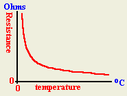
The relation is an inverse relation. When the temperature
is increased, the thermistor resistance decreases and when then temperature
is decreased the resistance is increased.
-
What is the main application of a thermistor?
A thermistor is used in the design of control-circuits which
require automatic switching that depends on temperature.
-
List applications that uses
thermistors
-
Fire alarm
-
Air conditions
-
Refrigerators
-
Draw a resistance-temperature graph
for a thermistor?
-
Draw a circuit that represents a
heat-operated switch using a thermistor?

-
Design a circuit that will operate
at cold-temperatures.
A thermistor usually has a resistance in
the order of 1M ohm at a cold state and has a typical resistance in the
order of 100 ohms at hot state.
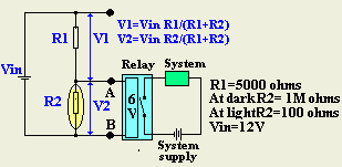
At cold temperature, the above circuit will
supply a voltage of V2=Vin R2/(R1+R2)=12*1M/(5000+1M)= 0.995 12=11.94 volts
which is above 6 volts and will energize the relay and thus the system. At
hot temperature, the circuit will supply a voltage of V2=Vin
R2/(R1+R2)=12*100/(5000+100)= 0.02 12=0.24 volts which less than 6 volts and
is not enough to energize the relay. Thus, the system is ON in cold
temperatures and OFF in hot temperatures.
-
Design a circuit that will operate
at hot-temperature.
A thermistor usually has a resistance in
the order of 1M ohm at a cold state and has a typical resistance in the
order of 100 ohms at hot state.
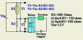
At cold temperature, the above circuit will
supply a voltage of V2=Vin R2/(R1+R2)=12*300/(300+1M)= 0.03% 12=0.0036 volts
which is below 6 volts and will not energize the relay and thus the system.
At hot temperature,, the circuit will supply a voltage of V2=V2=Vin
R2/(R1+R2)=12*300/(300+100)= 75% 12=9 volts which above 6volts and is enough
to energize the relay and thus the system. Thus, the system is OFF
in cold temperatures and ON in hot temperatures.
-
Explain the operation of the
circuit shown below?
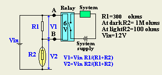
At cold temperature, the above circuit will supply a
voltage of V1=Vin R1/(R1+R2)=12*300/(300+1M)= 0.03% 12=0.0036 volts which is
below 6 volts and will not energize the relay and thus the system. At hot
temperature,, the circuit will supply a voltage of V1=Vin
R1/(R1+R2)=12*300/(300+100)= 75% 12=9 volts which above 6volts and is enough
to energize the relay and thus the system. Thus, the system is OFF
in cold temperatures and ON in hot temperatures.
-
Explain the operation of the
circuit shown below?
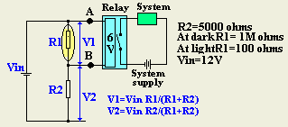
At cold temperature, the above circuit will supply a
voltage of V1=Vin R1/(R1+R2)=12*1M/(5000+1M)= 0.995 12=11.94 volts which is
above 6 volts and will energize the relay and thus the system. At hot
temperature, the circuit will supply a voltage of V1=Vin
R1/(R1+R2)=12*100/(100+5000)= 0.02 12=0.24 volts which less than 6 volts and
is not enough to energize the relay. Thus, the system is ON in cold
temperatures and OFF in hot temperatures.
-
-
What is a LDR?
LDR is a light dependent-resistor.
-
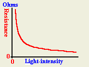
What is relation between the
resistance of an LDR and light intensity?
The relation is an inverse relation. When light-intensity
is increased, the LDR resistance decreases and when then light-intensity
is decreased the resistance is increased.
-
What is the main application of an
LDR?
An LDR is used in the design of control-circuits which
require automatic switching that depends on light.
-
List applications that uses LDR.
-
Counting system
-
Control Street lights in cities
-
Elevators
-
Draw a resistance-light intensity graph
for an LDR?
-
Design a circuit that will operate
at dark-time.
An LDR usually has a resistance in the
order of 1M ohm at dark and has a typical resistance in the order of 100
ohms at light-time.

At dark time, the above circuit will supply
a voltage of V2=Vin R2/(R1+R2)=12*1M/(5000+1M)= 0.995 12=11.94 volts which
is above 6 volts and will energize the relay and thus the system. At
daytime, the circuit will supply a voltage of V2=Vin
R2/(R1+R2)=12*100/(5000+100)= 0.02 12=0.24 volts which less than 6 volts and
is not enough to energize the relay. Thus, the system is ON in dark
and OFF in daytime.
-
Design a circuit that will operate
at daytime.
An LDR usually has a resistance in the
order of 1M ohm at dark and has a typical resistance in the order of 100
ohms at light-time.

At dark, the above circuit will supply a
voltage of V2=Vin R2/(R1+R2)=12*300/(300+1M)= 0.03% 12=0.0036 volts which is
below 6 volts and will not energize the relay and thus the system. At
daytime, the circuit will supply a voltage of V2=V2=Vin
R2/(R1+R2)=12*300/(300+100)= 75% 12=9 volts which above 6volts and is enough
to energize the relay and thus the system. Thus, the system is OFF
in dark time and ON in daytime.
-
Explain the operation of the
circuit shown below?

At dark, the above circuit will supply a voltage of
V1=Vin R1/(R1+R2)=12*300/(300+1M)= 0.03% 12=0.0036 volts which is below 6
volts and will not energize the relay and thus the system. At daytime, the
circuit will supply a voltage of V1=Vin R1/(R1+R2)=12*300/(300+100)= 75%
12=9 volts which above 6volts and is enough to energize the relay and thus
the system. Thus, the system is OFF in cold temperatures and ON in
hot temperatures.
-
Explain the operation of the
circuit shown below?

At dark,the above circuit will supply a voltage of V1=Vin
R1/(R1+R2)=12*1M/(5000+1M)= 0.995 12=11.94 volts which is above 6 volts and
will energize the relay and thus the system. At daytime, the circuit will
supply a voltage of V1=Vin R1/(R1+R2)=12*100/(100+5000)= 0.02 12=0.24 volts
which less than 6 volts and is not enough to energize the relay. Thus,
the system is ON in cold temperatures and OFF in hot temperatures.
-
What are the various types of
Reed switches?
1- Normally-opened (NO) Reed switches 2- Normally-closed (NC)
Reed switches
-
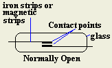
Describe the structure of
normally open Reed switch?
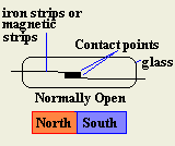
A normally open Reed switch consists of two magnetic strips
(e.g. iron) sealed in a glass tube. The two strips are not in
contact unless we apply a magnetic field that will work on attracting
the two strips.
-
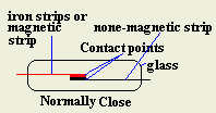
Describe the structure of
normally close Reed switch?
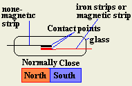
A normally close Reed switch consists of one magnetic strip
(e.g. iron) and another none-magnetic strip sealed in a glass
tube. The two strips are in contact unless we apply a magnetic
field that will work on separating the normal contact between the two
strips.
-
Describe the operation of a
normally open switch?
If a magnet is brought near a reed switch, it magnetizes each
iron strip. The result is that the two strips are attracted to
each other and they bend to touch each other
-
Describe the operation of a
normally close switch?
If a magnet is brought near a normally closed reed switch, it
magnetizes iron strip. The result is that the strip is pulled a
way from the none-magnetic strip causing the switch to be open.
-
Describe the structure of Reed
relay?
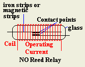
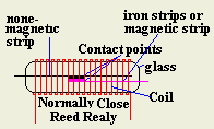
A Reed relay switch is a normal reed switch put inside a coil
of wire so that it can be operated by current passing throughout the
coil.
-
Design a simple burglar alarm
using Reed witches?
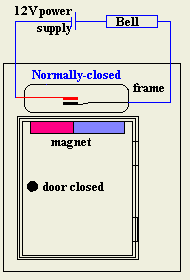
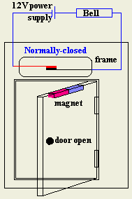
| A normally closed Reed switch can be
used in burglar alarms. The reed switch is fixed in the door frame
and a magnet in the door.
When the door closed the magnet keeps the NC reed switch open
and no alarm will present. However, when some one opens the
door, the magnet is displaced a way by the door. Thus the NC
reed switch returns its normal state closing the electrical
circuit which will activate the alarm system. |
 |
 |
-
What is meant by a potential
divider?
Potential divider is a circuit that allow us to use part of the voltage
of a power supply with a fixed e.m.f.
-
Explain the structure of a
potential divider that uses discrete resistors?
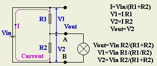
A potential divider that uses discrete resistors uses two
resistors in series connected to a fixed voltage power supply. The
output of the divider is taken across one of the two resistors as shown in
the diagram below.
-
Explain the operation of a potential divider that uses
discrete resistors?
The power supply generate a current that passes through the two
resistors in series. This current, given by I=Vin/(R1+R2), passes
through R1 and causes a voltage drop across R1 given by V1=IR1 and a voltage
drop across R2 given by V2=IR2. The output voltage between "A" and
"B" is given by Vout which is the same as V2.
-
Explain the structure and the action
of a potential divider that uses a rheostat (Potentiometer)?
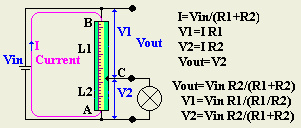
A potential divider that uses a rheostat (variable resistor) is connected to a fixed voltage power
supply over the full length of the resistor, Rt, and the output is connected
to the sliding terminal of the rheostat. As the slider is moved to
different positions, the voltage across length "L2" or resistor
"R2", (between "A" and "C") is proportional to
the resistance "R2" or length "L2".
-
What is the function of the
rheostat in the potentiometer?
The rheostat acts as a voltage divider which enables one to
choose the proper voltage. It used as a volume control in radios and
other electronic circuits
-
What is the relation between the
output voltage of a potential divider and the apparatus connected to it?
The potential difference across the apparatus is directly
proportional to the resistance across it.
-
|